- 您现在的位置:买卖IC网 > Sheet目录2001 > ISL12022IBZ-T7A (Intersil)IC RTC/CALENDAR TEMP SNSR 8SOIC
ISL12022
24
FN6659.3
November 22, 2011
User Registers (Accessed by
Using Slave Address 1010111x)
Addresses [00h to 7Fh]
These registers are 128 bytes of battery-backed user SRAM.
I2C Serial Interface
The ISL12022 supports a bi-directional bus oriented protocol. The
protocol defines any device that sends data onto the bus as a
transmitter and the receiving device as the receiver. The device
controlling the transfer is the master and the device being controlled
is the slave. The master always initiates data transfers and provides
the clock for both transmit and receive operations. Therefore, the
ISL12022 operates as a slave device in all applications.
All communication over the I2C interface is conducted by sending
the MSB of each byte of data first.
Protocol Conventions
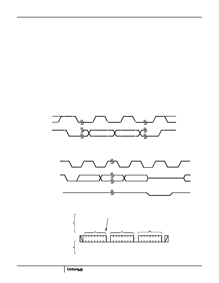
Data states on the SDA line can change only during SCL LOW
periods. SDA state changes during SCL HIGH are reserved for
indicating START and STOP conditions (see Figure 15). On power-
up of the ISL12022, the SDA pin is in the input mode.
All I2C interface operations must begin with a START condition,
which is a HIGH to LOW transition of SDA while SCL is HIGH. The
ISL12022 continuously monitors the SDA and SCL lines for the
START condition and does not respond to any command until this
condition is met (see Figure 15). A START condition is ignored
during the power-up sequence.
All I2C interface operations must be terminated by a STOP
condition, which is a LOW to HIGH transition of SDA while SCL is
HIGH (see Figure 15). A STOP condition at the end of a read
operation or at the end of a write operation to memory only
places the device in its standby mode.
An acknowledge (ACK) is a software convention used to indicate a
successful data transfer. The transmitting device, either master or
slave, releases the SDA bus after transmitting eight bits. During
the ninth clock cycle, the receiver pulls the SDA line LOW to
acknowledge the reception of the 8 bits of data (see Figure 16).
FIGURE 15. VALID DATA CHANGES, START AND STOP CONDITIONS
FIGURE 16. ACKNOWLEDGE RESPONSE FROM RECEIVER
FIGURE 17. BYTE WRITE SEQUENCE (SLAVE ADDRESS FOR CSR SHOWN)
SDA
SCL
START
DATA
STOP
STABLE
CHANGE
DATA
STABLE
SDA OUTPUT FROM
TRANSMITTER
SDA OUTPUT FROM
RECEIVER
8
1
9
START
ACK
SCL FROM
MASTER
HIGH IMPEDANCE
S
T
A
R
T
S
T
O
P
IDENTIFICATION
BYTE
DATA
BYTE
A
C
K
SIGNALS FROM
THE MASTER
SIGNALS FROM
THE ISL12022
A
C
K
10
0
11
A
C
K
WRITE
SIGNAL AT SDA
00 00
11 1
ADDRESS
BYTE
发布紧急采购,3分钟左右您将得到回复。
相关PDF资料
ISL12022MAIBZ
IC RTC/CALENDAR TEMP SNSR 20SOIC
ISL12022MIBZ-T7A
IC RTC/CALENDAR TEMP SNSR 20SOIC
ISL12022MIBZR5421
IC RTC/CALENDAR TEMP SNSR 20SOIC
ISL12023IVZ
IC RTC/CLDR TEMP SNSR 14-TSSOP
ISL12024IRTCZ
IC RTC/CALENDER 64BIT 8-TDFN
ISL12024IVZ
IC RTC/CALENDAR EEPROM 8-TSSOP
ISL12025IVZ
IC RTC/CALENDAR EEPROM 8-TSSOP
ISL12026IBZ-T7A
IC RTC/CALENDAR EEPROM 8SOIC
相关代理商/技术参数
ISL12022M
制造商:INTERSIL 制造商全称:Intersil Corporation 功能描述:Low Power RTC with Battery Backed SRAM, Integrated ±5ppm Temperature Compensation, and Auto Daylight Saving
ISL12022M_09
制造商:INTERSIL 制造商全称:Intersil Corporation 功能描述:Low Power RTC with Battery Backed SRAM, Integrated ±5ppm Temperature Compensation, and Auto Daylight Saving
ISL12022M_10
制造商:INTERSIL 制造商全称:Intersil Corporation 功能描述:Low Power RTC with Battery Backed SRAM,Integrated ±5ppm Temperature Compensation and Auto Daylight Saving
ISL12022MA
制造商:INTERSIL 制造商全称:Intersil Corporation 功能描述:Low Power RTC with Battery Backed SRAM, Integrated ±5ppm Temperature Compensation and Auto Daylight Saving
ISL12022MA_10
制造商:INTERSIL 制造商全称:Intersil Corporation 功能描述:Low Power RTC with Battery Backed SRAM, Integrated ±5ppm Temperature Compensation and Auto Daylight Saving
ISL12022MAIBZ
功能描述:实时时钟 REAL TIME CLK ENHANC CD ESD & MOISTURESIS RoHS:否 制造商:Microchip Technology 功能:Clock, Calendar. Alarm RTC 总线接口:I2C 日期格式:DW:DM:M:Y 时间格式:HH:MM:SS RTC 存储容量:64 B 电源电压-最大:5.5 V 电源电压-最小:1.8 V 最大工作温度:+ 85 C 最小工作温度: 安装风格:Through Hole 封装 / 箱体:PDIP-8 封装:Tube
ISL12022MAIBZ-T
功能描述:实时时钟 REAL TIME CLK ENHANC CD ESD & MOISTURESIS RoHS:否 制造商:Microchip Technology 功能:Clock, Calendar. Alarm RTC 总线接口:I2C 日期格式:DW:DM:M:Y 时间格式:HH:MM:SS RTC 存储容量:64 B 电源电压-最大:5.5 V 电源电压-最小:1.8 V 最大工作温度:+ 85 C 最小工作温度: 安装风格:Through Hole 封装 / 箱体:PDIP-8 封装:Tube
ISL12022M-EVAL
制造商:Intersil Corporation 功能描述:Low Power RTC with Battery Backed SRAM, Integrated 5ppm Temperature Compensation, and Auto Daylight Saving